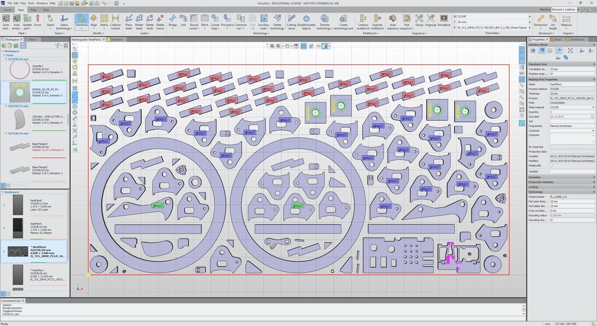
OmniWin is the most user-friendly CAD/CAM software for programming cutting machines.
- Oxyfuel cutting
- Plasma cutting
- Laser cutting
OmniWin is effective and economical for small quantities in mechanical and apparatus engineering as well as for just-in-time contract manufacturing with changing quantities in contract cutting companies.
OmniWin combines the highest technical flexibility with fast, efficient processing. At the same time, you will reduce your costs by minimizing material usage. The integrated operation with CAD, import and nesting for vertical and beveled parts permits a dramatic simplification of your working processes.
OmniWin is effective and economical for small production runs in the machine and manufacturing industry, as well as in just-in-time manufacturing with changing quantities at custom cutting operations. You save time and materials and work with easy operations. OmniWin is the ideal tool for production planning with thermal cutting for oxyfuel, plasma and laser cutting with CNC machines.
To learn more, please contact your local support.
If you would like to purchase OmniWin , please contact your local Messer Cutting Systems sales.

+ Intuitive user interface
+ 30% time saving through simple operation and clear processes!
+ Modern concept with workspace to keep overview over all the work
+ Clear database structure for the overview of parts, plans, offers and more
+ One shared database

+ Cutting processes oxyfuel, plasma, laser
+ Supports a wide range of marking methods such as dot peen, inkjet, punch, laser and plasma marking
+ Import of drilling operations
+ Integrated tool database
+ Drawing of drilling operations
+ Through holes, countersinks, tapping, deep hole drilling and spinning
+ Post processors with drilling support
+ Cutting multiple panels on one machine
+ Preconfigured machine profiles for standard machines
+ Preconfigured process databases
+ MesserHole ™ for precise parts

The OmniWin CAD/CAM system is technologically future-proof and ready for full integration into your Industry 4.0 applications. In interaction with OmniFab, you use OmniWin for the
+ pre-calculation of quotations,
+ live machine monitoring,
+ assignment to cutting jobs and
+ job monitoring as well as the
+ exchange of data with your ERP system
+ One shared database based on Microsoft SQL database technology
+ Multi users by modern Single seat and Network topology with floating license model and database
+ Multi language support: German, Danish, English, Spanish, French, Portuguese, Swedish, Turkish, Dutch, Chinese, Norwegian, Slovenian, Polish, Czech, Tsakhurian
Contact
YouTube Videos Playlists
Downloads
Find out more about Product Automation Solutions and your Digital Workflow: click here for further details and to visit our download area.
OmniWin Features
+ Single/Multi import of AutoCAD files (.DXF, .DWG, .DWF,) DSTV files (.NC, .NC1, .XML), Excel files (.XLS), or IGES files (.IGS, .IGES), Solidworks* files (.SLDPRT, .SLDASM), PNL files
+ Individual import of DIN and ESSI drawings
+ Reading of pictures (JPG, PNG,) scans with recognition of component contours
+ Automatic layer translation
+ Automatic error corrections
+ Adoption of component metadata
+ Easy import via SolidWorks* or Autodesk Inventor** interface
+ Transfer technologies of nested components to identical components
+ Unfolding of bending parts
+ Disassembly of modules
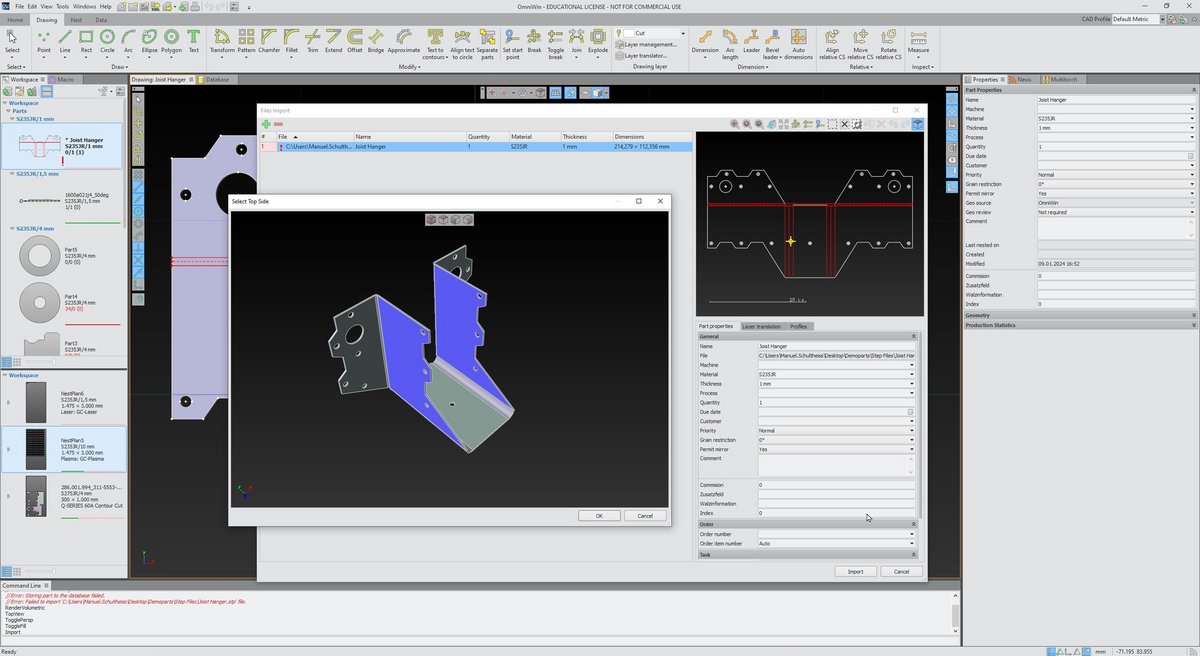
3D Import of:
+ STEP / STP files (AP203, AP214, AP242)
+ Siemens SolidEdge (V18 – SE 2023)
+ Autodesk Inventor (V11 – 2024)
+ Dassault Systèmes CATIA (V5 R8 to V5–6 R2023)
+ Siemens NX (11 – NX 2306)
+ Siemens Parasolid (9.0 – 35.0.149)
+ PTC Pro/E (16 – Creo 10.0)
+ Rhinoceros 3D (version 2 to 7)
Minimum requirement for 3D import is OmniWin Edition Enhanced
| * A SolidWorks license required with installation on the same PC |
| ** An Autocad Inventor or viewer required with installation on the same PC |
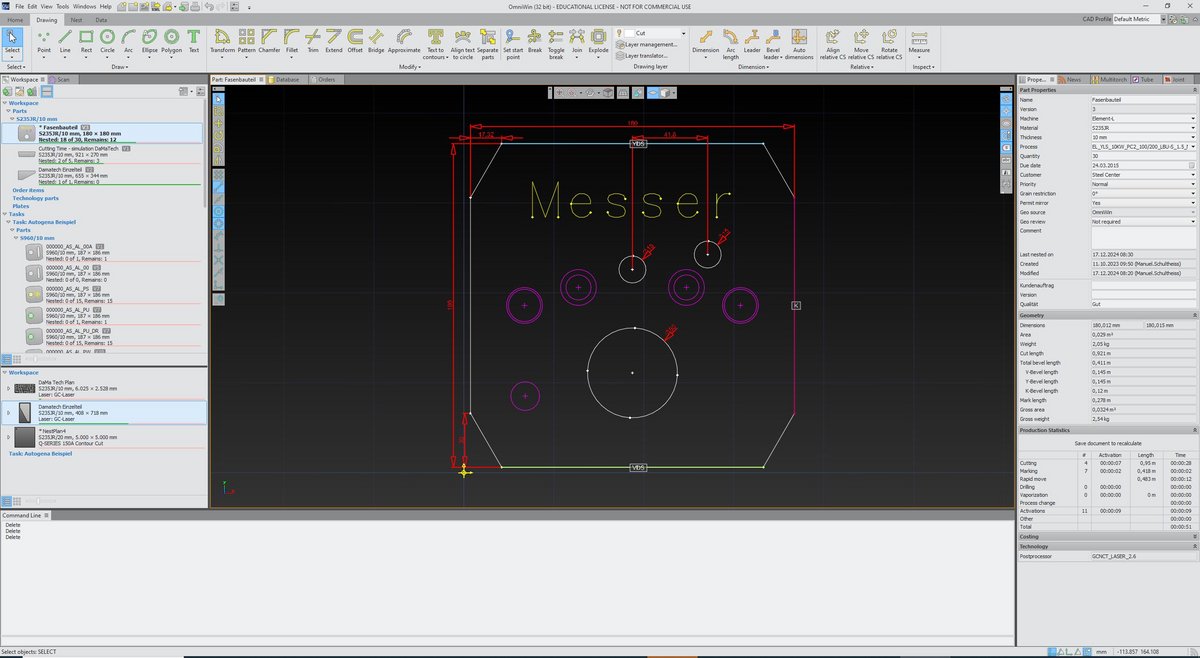
+ Numerous positioning, drawing, grouping and labeling functions
+ Parameterizable macros
+ Automatic dimensioning of components and plates
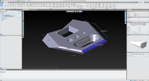
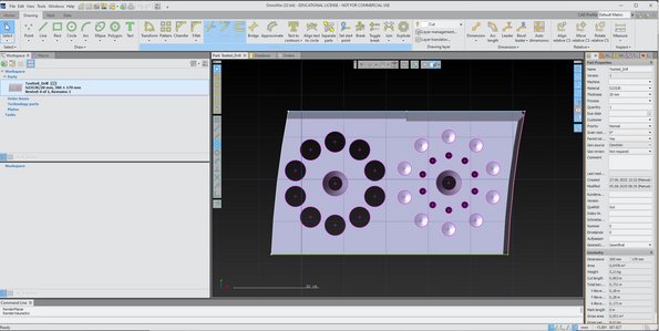
+ 3D view of vertical and bevel components
+ Extensive drawing functions for geometric shapes and labelling
+ Support of absolute and relative as well as polar and orthogonal coordinates
+ Conversion of text objects into closed contours and/or line contours
+ Alignment of text objects to arcs
+ A wide range of Zoom, Snap, Convert and Group functions e.g. trimming of protruding contours
+ Insertion of dimensioning objects
+ Definition of bevel information and quality attributes on sub-contours
+ 3D view of vertical cut or bevel parts
+ Optional setting of start points per contour
+ CAD profiles to support individual configurations

+ Configurable technology database
+ Copy, mirror, rotate and move with collision control
+ Component and contour sequences automatically optimized based on rules or set manually
+ Automatically optimized component, inner contour and process sequence
+ Automatic nesting of orders and projects
+ Reduction of non-productive times by minimizing rapid traverse
+ Reduction of the up and down movements of the torch with collision avoidance
+ Individually adjustable shapes, parameters and positions of lead and cut-out flags
+ Changing the cutting direction
+ Enable and disable contours
+ Automatic rounding of corners
+ Vaporization (Laser)
+ Simulation of the nesting plan

Design and data import
Experience how easy bevel cutting can be. Work in your familiar OmniWin environment and seamlessly integrate the entire beveling process. Import your bevel components directly from CAD quickly and without detours. Design and modify your components with the highest precision. Thanks to the direct display of the bevel geometries, you always have a full overview.
+ Fully integrated bevel cutting in the familiar OmniWin working environment
+ Direct import of bevel parts via CAD import
+ Design and modification of bevel parts
+ Representation of the bevels on parts
Cutting and manufacturing technologies
Increase your efficiency with every cut. Optimally nest bevel parts and use state-of-the-art lead-in, lead-out and corner technologies – from I- to VDS, VAS, YDS, YAS, X- to K-bevels as well as variable bevels.
Benefit from integrated bevel process databases for consistently high component quality. Assign specific quality levels to your bevel geometries and get the most out of your cutting process. Intelligently sequence multiple cuts and rely on full compatibility with all Messer bevel cutting heads for laser, plasma and oxyfuel.
+ Nesting of bevel part
+ Lead-ins, Lead-out and corner technologies for I-, VDS, VAS, YDS, YAS, X, K and variable bevels
+ Integrated bevel process databases for optimal part quality
+ Quality assignment for bevel geometries for cutting optimization
+ Sequencing of multiple bevel cuts
+ Support for all Messer bevel cutting heads (Laser, Plasma, Autogen)
Planning and reporting
Reliably calculate the production time of your bevel plans. Integrate the display of the chamfers directly into your automated production reports.
+ Optional production time calculation for bevel plans
+ Display of bevels in automated production reports
Bevel cutting only available with Option Bevel

+ Completely integrated development of three-dimensional bodies in the plane
+ Large number of geometric bodies typical for apparatus and tank construction
+ Sorting of the geometries according to criteria in categories and subcategories
+ Fully integrated unfolding of three-dimensional solids in the plane
+ Large number of geometric solids typical for apparatus and tank construction
+ Sorting of geometries according to criteria in categories and subcategories
Only available with the Option Unfold

+ Optimization of cutting quality through the use of advanced technologies
+ Various stitch types for the different cutting technologies
+ Single and multiple stitches, manually and automatically applied
+ Thermal pre-piercing or pre-drilling for lead-ins
+ Bridges, also crossed
+ Common cuts
+ Corner loops
+ Rounding of corners
+ Any remnant plate geometries
+ Any plate geometry
+ Skeleton cuts
+ Cutting of stone mold cutting
Technology functions only available in OmniWin Professional
+ Tool sequencing
+ Optimize part sequence
+ Change contour sequence
+ Optimize sequence for heat distribution
+ Grouping
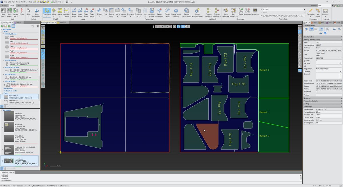
+ Marking of remnant plates
+ Automatic creation of remnant plate
+ Crop cuts
+ Manual splitting of remnant plates
+ Automatic remnant plate reports
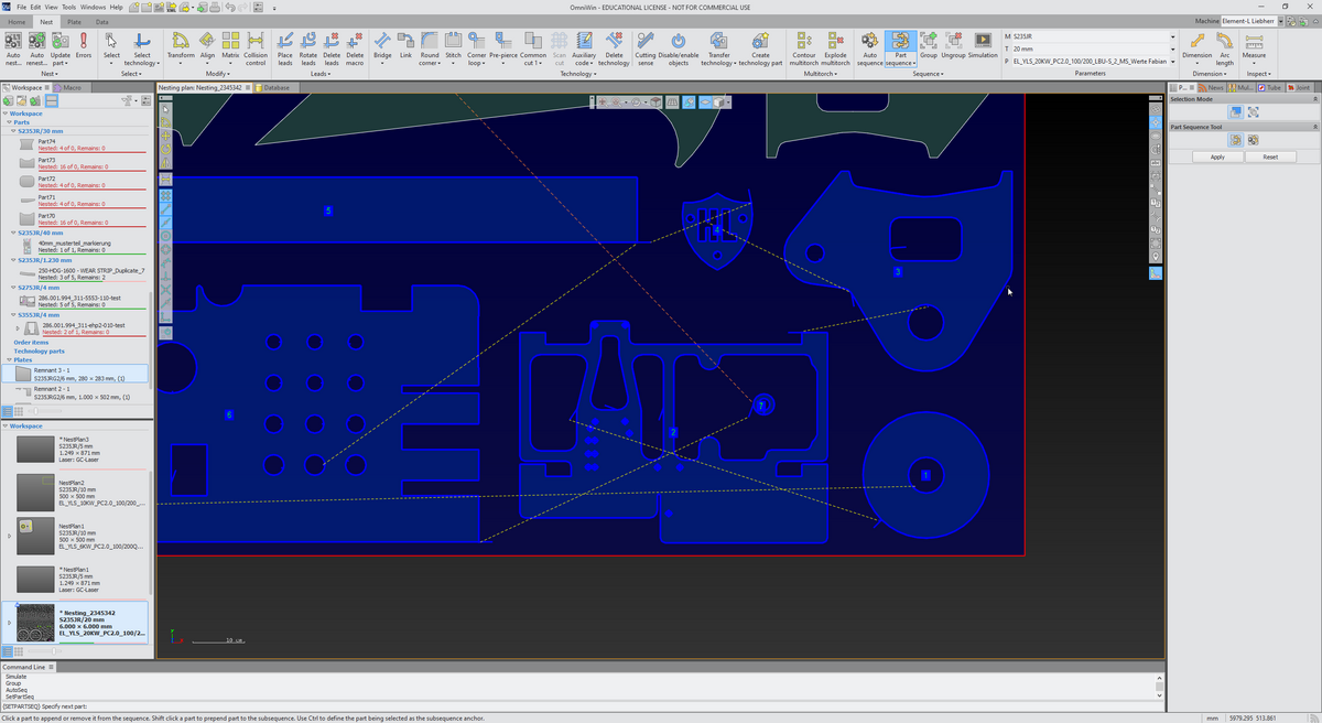
+ Simulate tool movement
+ Check the cutting sense and the sequence of processing of the contours in your nesting plan
+ Adapt the speed of the simulation progress
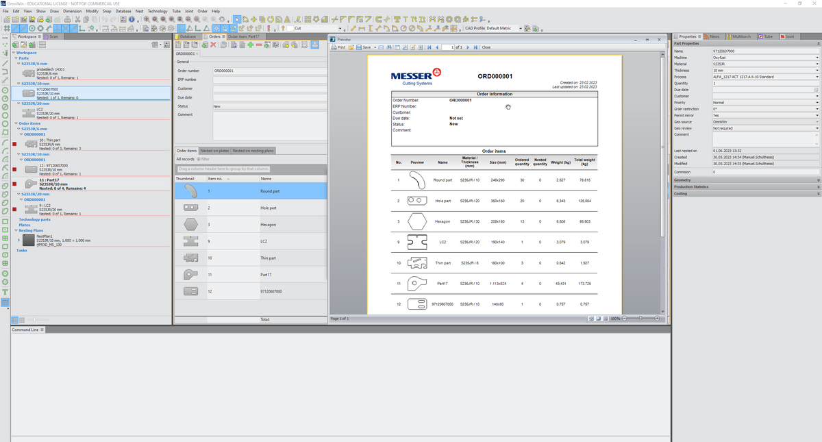
+ Fully integrated order entry and oder management
+ Work order processing with order database
Only available in OmniWin Enhanced and OmniWin Professional
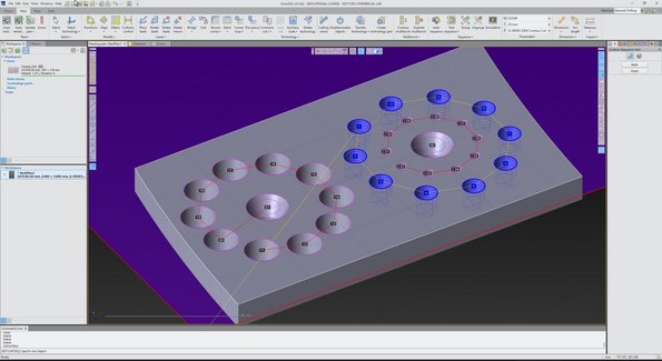
Create drilling operations in CAD mode
Design and define drilling tasks directly within your CAD environment. Drill holes can be inserted into drawings, converted from existing points, or generated via the command line for maximum flexibility. A wide range of drilling types such as through holes, tapped holes, blind holes, and deep drilling are fully supported, including variations with countersinking. Every detail can be set precisely, and all operations are displayed in 3D, ensuring complete accuracy and transparency, even down to the thread representation.
+ Creating drill holes in drawings
+ Converting points to drill holes
+ Creating drill holes from the command line
+ Set drill point properties:
+ Marking hole
+ Through-hole
+ Through-hole with countersink
+ Tapped hole
+ Tapped hole with countersink
+ Blind hole drilling
+ Blind hole drilling with countersink
+ Deep hole drilling (deep hole drilling)
+ 3D representation including thread
Efficient tool and process management
The OmniWin Option Drill includes an integrated drill tool database, making it simple to select and manage tools for every job. Drill holes are clearly visualized in both drawings and nesting layouts, giving operators full control over the process. Users can manually sequence drill holes, group them for efficiency, or rely on the automatic sequencing function, which optimizes the drilling order—for example, when tapping or creating pilot holes before thermal cutting. With built-in machining time calculation, production planning becomes more accurate, predictable, and cost-efficient.
Management of drilling tools
+ Integrated drill database for drilling tools
Creation and modification of nesting plans
+ Display of drill holes in drawings and nesting plans
+ Manual sequencing of drill holes and the ability to group drillings
+ Automatic sequencing of the drilling sequence (e.g. for tapped holes or pre-drilling before thermal cutting)
+ Production time calculation for drilling operations
+ Post-processors for Messer Global Control and Global Connect machines
+ Generation of NC Code for nesting plans (straight and bevel cutting)
Seamless integration into your production
Designed for maximum compatibility, the OmniWin Option Drill works seamlessly with Messer Global Control and Global Connect machines. Dedicated post-processors ensure reliable communication and precise NC code generation. Whether drilling vertically or at an angle, the module guarantees high-quality results and smooth integration into existing nesting plans—allowing your production line to achieve superior performance with minimal effort.
Only available with Option Drill
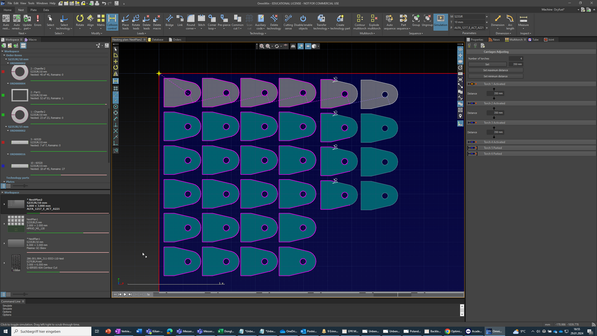
+ Supports machines with and without automatic carriage positioning
+ Changing of torch distances in the same plan
+ Dynamic connection and disconnection of torches
+ Automatic nesting for multiple torch heads

+ Individual user-based preview of NC programs and export of NC part programs, CSV, XML, DXF and DWG files for nesting plans
+ Machine profile based settings of production data storage locations
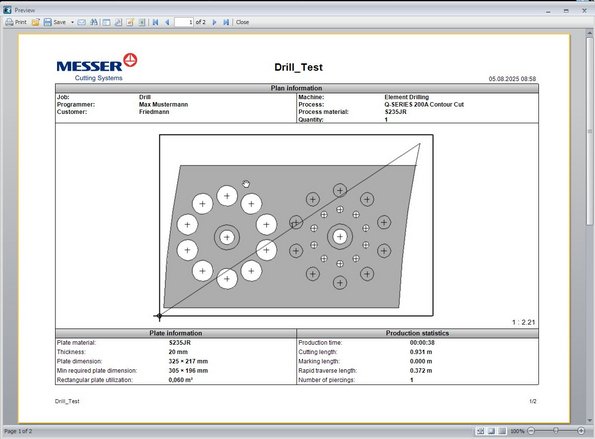
+ Preconfigured reports for parts and nesting plans
+ Automatically configured printing of nesting plan reports
+ Integrated report editor to customize the existing reports or to create your own reports
Standard | Enhanced | Professional | ||
| CAD | Professional CAD Part and Plate Creation | X | X | X |
| 3-D Visual Rendering of parts and plates | X | X | X | |
| Standard Shapes Library | X | X | X | |
| Text conversion for Cut-outs or Marking tasks | X | X | X | |
| CAD Import - DXF, DWG, IGES, DSTV | X | X | X | |
| Import of SolidWorks* Part (SLDPRT) and Assembly (SLDAMP), Import of Autodesk Inventor* parts and assemblies | X | X | X | |
| Import of 3D drawing formats** (STEP, SolidEdge, and others) | X | X | ||
| Read and Translate Administration Data | X | X | X | |
| Import of images in BMP, JPG, PNG or TIF file formats | X | X | X | |
| Import of nesting plans as DXF i.e. Auto Desk TRUNEST | X | X | X | |
| Reverse import of CNC files to DXF | X | X | X | |
| Automatic dimensioning of parts and plates | X | X | X | |
| CAD and Nesting | MS SQL Database for Parts, Nestings, Plates, Profiles and Machines | X | X | X |
| Fast Reports® Creator for professional reports | X | X | X | |
| Professional designed workspace | X | X | X | |
| Short Cut Keys | X | X | X | |
| Extensive dimensioning | X | X | X | |
| Extensve Snap Modes | X | X | X | |
| Manipulator Tool for rotation, copy, move and mirror | X | X | X | |
| Nesting | Process Database | X | X | X |
| Messer Hole Technology supports True Hole® or Contour Cut | X | X | X | |
| Production Time Estimation | X | X | X | |
| Costing | X | X | X | |
| Automatic Lead-in/out with Customization | X | X | X | |
| Cut Plan Simulator | X | X | X | |
| Interactive nesting (Row and Column, Pattern Matrix) with Single or Multi-Torch | X | X | X | |
| Collision Avoidance | X | X | X | |
| Process Optimization | X | X | X | |
| Modify Part, Interior Profile or Marking Sequence | X | X | X | |
| Technology Parts | X | X | X | |
| Manual Crop Cut | X | X | X | |
| Work Order Processing with Order Database | X | X | ||
| Automatic Nesting | X | X | ||
| Excel import of parts, order items and plates | X | |||
| Stone Mold Cutting | X | |||
| Stitches, Bridges, Common Cut, Corner Loops, Chain Cut, Automatic Corner Rounding | X | |||
| Skeleton Cut Up | X | |||
| Pre-Piercing and Pre-drilling (Option Drill required) | X | |||
| Remnant Plate Creation with Auto Crop Cut | X |
| * A SolidWorks license is required with installation on the same PC |
| * An Autocad Inventor or viewer is required with installation on the same PC |
+ Option Bevel - Bevel Part Creation (download factsheet)
+ Option Unfold - Unfold 3D Industrial Fittings
+ Option Boiler End (requires Option Bevel) - Dome Cutting
+ Option Mill - 2.5D Milling Support for Pocket Milling and Through Hole Milling (US only)
+ Option Drill - Drill support (download factsheet)
Hardware requirements:
+ 16 GB RAM, 20 GB hard disk space, 2 GHz CPU with 4 cores.
+ Screen resolution at least 1280 x 960 pixels, recommended 1680 x 1050 pixels or more
+ Graphics card supporting OpenGL 1.1 or higher without shared memory
+ USB port for local software protection dongle or network access to a license server
Supported operating systems:
+ Windows 10/11 64 bit
Software requirements:
+ Microsoft Edge
+ Microsoft .NET Framework 4.8
+ Microsoft Access Database Engine 2016
+ Microsoft Visual C++ 2015-2022 Redistributable (x86) (vc_redist.x86.exe)
+ Microsoft SQL Server 2017 LocalDB or higher
+ Microsoft SQL Server 2012 Native Client
Further Products


The Messer Experience
Although Messer Cutting Systems is known for a 100 per cent focus on the requirements of cutting machine users, the machine is only one component of the overall solution.
Messer Cutting Systems offers the most diverse solutions portfolio in the thermal cutting industry with machines, software solutions, original spare and wear parts, a broad spectrum of services and numerous additional options to upgrade your machine in an optimal way.


Automation
Maximise your machine utilisation and increase productivity with our modular automation solutions.